
Intermediate Casing Cementing Procedure
1. PURPOSE
This procedure provides a complete, API-aligned workflow for safely and effectively cementing an intermediate casing string in an oil or gas well.
A properly executed cementing job ensures the following:
Correct Casing Placement and Centralization: The casing is positioned as designed to maintain a uniform annulus for a consistent cement sheath.
Effective Zonal Isolation: The cement creates a durable barrier that prevents fluid migration between formations and the wellbore.
Accurate Slurry Placement: Cement is placed precisely across the intended intervals, including the shoe track and any critical zones.
Structural Support and Integrity: The cement supports and protects the casing from collapse, pressure loads, and corrosive fluids.
Complete Mud Displacement: Drilling mud and other fluids are efficiently removed and replaced with cement to promote good bonding.
Reliable Plug and Float Equipment Performance: Plug release and float equipment functions are confirmed and monitored throughout the operation.
Clean Circulation and Proper Fluid Conditioning: Circulation ensures clean wellbore surfaces and stable downhole conditions for cementing.
Prevention of Sustained Annular Pressure (SAP): The cement achieves adequate strength and volume to avoid trapped pressure.
2. PRE-JOB ENGINEERING PREPARATION
2.1 Verify Casing Program
Ensure the casing string meets all design requirements:
Confirm casing grade, weight, connections, and torque limits.
Verify the connection makeup torque envelope (minimum, optimum, maximum).
Review the centralizer placement plan to achieve the required stand-off.
Check float equipment specifications and availability.
Confirm the selected fill policy (autofill or manual fill).
2.2 Cement Design Validation
Ensure the cement system is engineered for the expected downhole environment:
Validate cement class, density, water ratio, and additive package.
Confirm slurry testing meets API RP 10B-2 requirements, including rheology, thickening time, free water, fluid loss, and compressive strength development.
Review compatibility tests between cement and drilling fluid.
Spacer and Pre-Flush
Ensure the design, composition, and volumes of pre-flush and spacer fluids are appropriate for mud removal and contamination control.
Volume Calculations
Calculate cement, spacer, and displacement volumes using final TD and caliper logs.
Add the required excess volume (typically 10–30%) based on offset data and hole conditions.
2.3 Operational Checks
Surface Equipment
Confirm pumps, blenders, and cementing units are tested and rated for planned pressures.
Verify calibration of densitometers, flowmeters, and pressure recorders.
Downhole Tools
Inspect the cementing head, plugs, and release systems for integrity.
Safety and Contingency
Review NPT contingencies (losses, equipment failure, early set).
Confirm all personnel understand JSA and emergency actions.
Operational Readiness
Validate annular volumes, pump schedule, plug release volumes, expected bump pressure, and returns monitoring plan.
3. CASING RUNNING OPERATIONS
3.1 Casing Running and Monitoring
Connection Makeup
Use power tongs and follow the specified torque envelope.
Record torque and turns for each connection.
Casing Fill and Differential Pressure Control
Keep the casing filled to prevent collapse.
Use autofill equipment when available; otherwise, fill manually at defined intervals.
Monitor return flow during filling.
Operational Monitoring
Monitor hook load, drag, and overpull for signs of wellbore issues.
Confirm shoe depth and recalculate if necessary.
Perform rotation or reciprocation checks when safe to ensure mobility.
Final Landing
Verify the casing shoe depth and secure the casing in the slips.
Complete space-out for proper equipment alignment.
3.2 Centralization and Stand-Off Control
Centralizer Installation
Install centralizers per program to maintain ≥67% stand-off.
Confirm that the centralizer type suits the hole conditions.
Critical Sections
Increase centralizer density in the build section, horizontal intervals, and near the shoe track.
Integrity and Modeling
Inspect centralizers for damage before and during running.
Ensure planned stand-off matches the engineering model.
4. WELLBORE CONDITIONING
4.1 Pre-Cement Circulation and Fluid Quality
Establish Stable Circulation
Start circulation gradually, then increase to the highest safe rate.
Confirm stable returns (consistent flow, density, and pressure).
Optimize Mud Properties
Adjust density, viscosity, and gels for effective mud removal.
Minimize solids and eliminate entrained gas.
Cleaning Verification
Monitor flowline and shakers for cuttings.
Ensure pumped and returned volumes match.
Perform a check trip or short trip if required.
4.2 Circulation Time and Rate
Circulate for the planned number of bottom-up cycles to stabilize temperature and condition fluids.
Use rates that approach turbulent or efficient plug-flow conditions when feasible.
4.3 Pressure Monitoring
Compare the final circulating pressure with the expected values.
Keep ECD within the safe operating window.
5. CEMENTING EXECUTION AND VERIFICATION
5.1 Plug Verification
Bottom and Top Plugs
Confirm correct size, material, and condition.
Ensure fins and wiping elements are intact.
Verify proper storage and handling.
Bottom Plug Diaphragm
Check rupture rating.
Loading Sequence
Confirm that the plugs are loaded into the correct chambers in the cementing head.
5.2 Cementing Head Function Checks
Ensure chamber alignment and seal integrity.
Confirm indicator pins and release systems function properly.
Verify the head’s pressure rating exceeds MACP.
6. FLUID AND PLUG SEQUENCE (API-Aligned)
Casing is filled with drilling mud.
Pre-flush, wash, or spacer is pumped to clean surfaces and isolate mud.
The bottom plug is released after the spacer is pumped.
Cement slurry is pumped behind the bottom plug.
The top plug is released after the cement volume is pumped.
Displacement fluid is used to push cement to the final position.
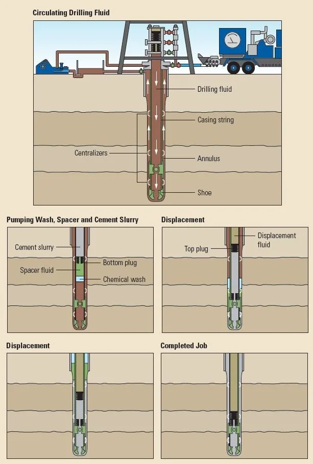
Credit: https://www.slb.com/resource-library/oilfield-review/defining-series/defining-cementing
7. BOTTOM PLUG RELEASE ASSURANCE
7.1 Safe Release
Announce plug release.
Activate the release mechanism.
Confirm release via indicator pin or mechanical feedback.
Record time and strokes.
7.2 Pumping Spacer and Cement
Pump the full planned cement volume for lead and tail slurries.
Maintain programmed rates and monitor pressures.
7.3 Landing Confirmation
Identify a clear pressure spike when the plug lands.
Confirm diaphragm rupture by a subsequent pressure drop.
Record strokes and landing pressure.
8. CEMENT SLURRY PUMPING
8.1 Main Pumping
Pump cement at the planned rate and density.
Continuously monitor friction pressure, pump rate, slurry density, and ECD.
8.2 Returns Monitoring
Ensure consistent returns at the flowline.
Match pumped and returned volumes.
Record stroke counts accurately.
9. TOP PLUG RELEASE ASSURANCE
9.1 Safe Release
Announce the release and activate the system.
Verify visual confirmation and record time and strokes.
9.2 Pumping Displacement Fluid
Begin displacement immediately after plug release.
Maintain a steady rate to complete placement.
9.3 Landing Confirmation
Observe the pressure rise as the top plug nears the bottom plug.
Record a sharp pressure spike when they stack.
10. DISPLACEMENT AND BUMPING THE PLUG
Pump the exact displacement volume.
Reduce the rate near completion.
Identify the bump pressure and verify it meets the estimates.
Hold pressure for several minutes, then bleed off and secure the well.
11. POST-JOB VERIFICATION
11.1 Flowback Monitoring
Monitor for any flowback.
Zero flowback confirms float equipment integrity.
11.2 Cement Returns (If Circulated to Surface)
Observe color and consistency.
Confirm no contamination or unexpected losses.
11.3 Documentation
Record:
Stroke counts, volumes, and pump times.
Landing pressures and hold-test results.
Plug release times and confirmation.
Final static pressure and returns.
12. WELL SECURING AND WOC
Close and secure all valves.
Allow the cement to cure for the required WOC time per lab results.
Avoid pressure testing before the cement reaches the required strength.
13. CRITICAL ASSURANCE POINTS
Bottom Plug:
Release confirmed.
Correct landing pressure signature.
Diaphragm rupture verified.
Top Plug:
Release confirmed.
Correct displacement volume pumped.
Sharp landing pressure signature.
Float Equipment:
Holds pressure during the post-bump pressure test.
Disclaimer: This guide synthesizes and paraphrases industry best practices from referenced sources and attached documents for educational and field-reference purposes only. It does not reproduce copyrighted material verbatim and is not official company policy or engineering advice. All information belongs to the original authors and publishers who retain full rights. No claim of original authorship is made for referenced concepts, and the document is distributed in good faith for drilling professionals.