Motor Stalling vs. Hydrolocking
Share Your Experience and Comments
Key Questions Answered in This Article
What is the precise mechanical and hydraulic difference between a motor stall and a true hydrolock?
Can a mud motor hydrolock off-bottom without experiencing a mechanical torque stall?
How do stator elastomer swelling, thermal expansion, and power section lobe configurations trigger downhole lockups?
How do modern Even-Rubber-Thickness (ERT) and All-Metal stators alter motor failure modes?
What specific, field-proven engineering controls eliminate motor stalls and prevent surface pump relief trips?
Downhole Energy Flow
In upstream drilling operations, positive displacement motors (PDMs) drive the bit downhole by converting hydraulic energy into mechanical torque:
While a mechanical stall is a common operational hurdle, true hydrolocking represents an absolute fluid blockade that halts operations, risks drill pipe fatigue, and damages expensive BHA tools.
1. Motor Stalling vs. Hydrolocking
Field personnel must distinguish between standard torque stalls and true hydraulic lockups to diagnose downhole issues accurately:
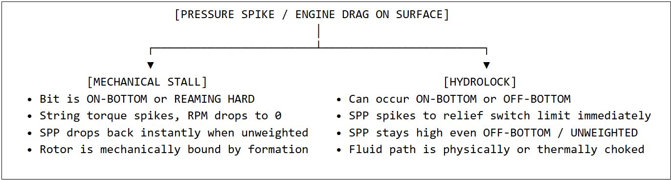
Motor Stall: Occurs when the mechanical torque resistance at the bit or drag encountered while back-reaming tight ledges exceeds the motor's output torque. The rotor stops turning inside the stator, but fluid attempts to pass through, causing standpipe pressure (SPP) to spike sharply and risking surface pump relief trips.
Hydrolock (Fluid Lock): The standpipe pressure (SPP) spikes following a mechanical stall or an independent fluid blockade. The fluid gets trapped inside the sealed in the helical cavities between the rotor-stator and cannot move. It can also be a combined effect of swelling elastomers, mechanical jamming, or heavy annular pack-off, shutting the fluid passage completely. This locks the incompressible mud column, subjecting the drill string to mechanical shock and risking stator elastomer damage ("chunking").
Can Hydrolock Occur Without a Torque Stall?
Yes. While a mechanical stall typically leads to hydrolock, hydrolock does not require a torque stall to occur. It can originate independently from severe fluid restriction:
Off-Bottom Elastomer Swell: High bottom-hole temperatures (BHT) and Oil-Based Mud (OBM) cause severe rubber swelling, closing the internal rotor-stator channels completely before the bit ever touches bottom.
External Hydraulic Blockades: Annular pack-offs from sticky cuttings or solid debris plugging bit nozzles trap the mud column, forcing surface pumps to lock up and stopping the rotor as a secondary effect of fluid blockage rather than formation torque.
2. Motor Construction Intricacies
Motor mechanical design, thermal dynamics, and internal tolerances within the power section play an important role in the downhole hydraulic lockups.
Standard Elastomers vs. Modern Stator Technologies
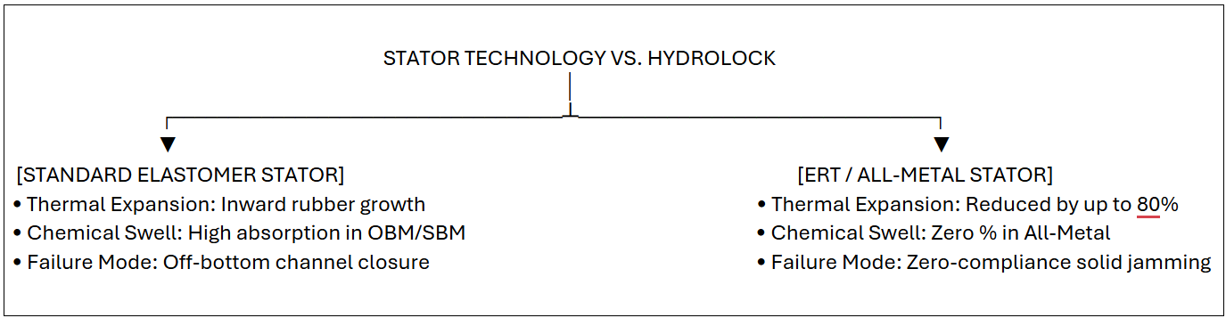
Conventional Elastomers (NBR / Standard HNBR): Standard mud motors use a steel rotor turning inside a thick, molded rubber stator. High BHT expands the rubber inward much faster than the steel housing expands outward, while exposure to OBM/SBM causes the elastomer to absorb hydrocarbons and swell. Internal fluid channels shrink or close entirely, driving up the off-bottom pressure and triggering instant lockup.
Even-Rubber-Thickness (ERT) & All-Metal Stators: ERT stators utilize a thin, uniform rubber layer over a profiled steel housing, while all-metal stators eliminate rubber entirely. These designs reduce thermal expansion by up to 80% and eliminate chemical swelling. However, because all-metal stators lack rubber compliance (flexibility), solid debris or rotor flexing under extreme loads causes an instant, rigid mechanical freeze, creating a secondary hydrolock.
Lobe Configurations & Stage Designs
High Lobe Configurations (e.g. 7:8, 9:10): Deliver higher torque at lower RPMs for PDC bits but feature tighter internal fluid pockets. Solid loads, cuttings bridges, or minor rubber expansion can easily choke these narrow channels.
Stage Counts: Multi-stage motors deliver higher differential pressure. When stalled under high differential pressure, trapped fluid across stages deforms the elastomer lobes, causing permanent mechanical chunking.
3. Field Engineering Mitigations & Action Plan
1. Automate Pressure Management (Differential Pressure Mode)
Switch surface auto-driller systems from standard WOB/Hookload control to continuous Differential Pressure Control Mode. Setting a tight differential target (e.g., 450 psi over off-bottom pressure) enables the auto-driller to instantly modulate drawworks feed or pull back the moment differential pressure surges, eliminating operator reaction lag and preventing relief-valve trips.
2. Mitigate Lateral Drag (Hydraulic Agitators)
Position a fluid-pulsing tool (agitator/shock tool system) ~600 ft above the BHA. The tool converts mud-flow pulses into gentle, continuous axial vibrations along the drillstring, overcoming static wall friction in long laterals and enabling smooth weight transfer without destructive weight surges.
3. Optimize Hole Cleaning & Back-Reaming Hydraulics (Asymmetrical Bit Nozzling)
Configure PDC bits with asymmetrical nozzle arrays. Directing targeted high-velocity fluid jets across the bit face and toward the gauge creates asymmetric hydraulic cross-flow, aggressively clearing cuttings ledges through the junk slots and preventing fluid pack-offs around the motor face during back-reaming.
4. Account for Thermal & Chemical Swell (Power Section Sizing)
When operating mud motors in high-density OBM/SBM at elevated bottom-hole temperatures (BHT), specify pre-run undersized rotors (or deploy Even-Rubber-Thickness / All-Metal stators). Sizing the rotor fit accounts for elastomer swell and thermal expansion downhole, maintaining optimal fluid channels and preventing off-bottom lockup.
4. Field Troubleshooting Guide
In field operations, distinguishing between a pure mechanical torque stall and a hydraulic lockup (hydrolock) is critical because applying the wrong corrective action.
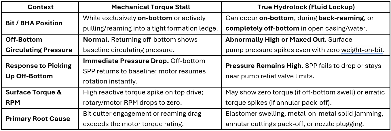
4.1. Diagnostic Comparison: Mechanical Stall vs. Hydrolock
The fastest way to differentiate between the two on the rig floor is to observe bit position, string torque, and off-bottom vs. on-bottom standpipe pressure (SPP).
Key Diagnostic Indicators
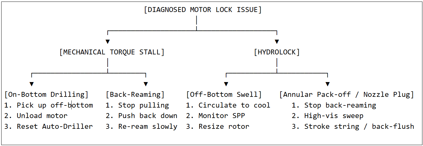
4.2. Field Remedial Action Matrix
4.3. Step-by-Step Remedial Actions in the Field
Scenario A: Resolving a Mechanical Torque Stall
When the motor stalls due to formation over-torque while drilling ahead or reaming:
1. Immediately Pick Up Off-Bottom (Unload the Motor):
Action: Rapidly hoist the drill string to pull the bit off the formation face, taking care not to exceed safe overpull limits.
Target: Watch the Standpipe Pressure (SPP) gauge to ensure it drops back down to your baseline off-bottom circulating pressure.
Caution: Never leave the pumps running against a stalled rotor for more than a few seconds. Trapped fluid under extreme differential pressure will deform and chunk the stator's elastomer.
2. Re-Establish Motor Rotation:
Hold the bit off-bottom and allow all reactive torque in the top-drive and drill string to bleed off completely. Confirm that your off-bottom SPP is stable and surface/downhole RPM has recovered before proceeding.
3. Re-Engage Bottom Slowly & Adjust Auto-Driller Settings:
Lower the bit back to the bottom gently.
Field Adjustment: To prevent repeat stalls, switch the surface auto-driller from WOB/Hookload mode to 'Differential Pressure Control Mode' and set a target differential limit (e.g., 450 psi above off-bottom SPP). This enables the system to automatically adjust drawworks feed the instant torque builds, eliminating human reaction lag.
Scenario B: Resolving a Hydrolock Event
Resolving a hydrolock requires targeted troubleshooting depending on whether the blockage is internal (stator/rotor fit) or external (annulus/nozzles):
1. If Hydrolocked OFF-BOTTOM (Elastomer Swell / Thermal Expansion)
Immediate Action: Stop down-feed immediately and do not attempt to force the bit to the bottom.
Thermal Mitigation: Lower the pump rate slightly and circulate cooler surface mud downhole to reduce bottom-hole temperature (BHT) and shrink the thermally expanded rubber.
Chemical Assessment: Check the Oil-Based Mud (OBM) oil-to-water ratio and aromatic content. If standard Nitrile or HNBR elastomers are absorbing hydrocarbons, mud conditioning may be required.
Long-Term Fix: If off-bottom SPP remains maxed out, pull out of hole (POOH) to resize the motor power section with a pre-run undersized rotor, or upgrade to an Even-Rubber-Thickness (ERT) or All-Metal stator.
2. If Hydrolocked During Back-Reaming (Annular Pack-Off)
Immediate Action: Stop pulling up-hole immediately. Slacking off (moving down-hole a few feet) often breaks up the compacted cuttings ledge bridging the annulus.
Hole Cleaning: Increase the circulating rate to the maximum allowable parameters and pump a high-density, high-viscosity sweep to clear accumulated cuttings ledges out of the narrow annular space.
Nozzle Layout: If pack-offs recur frequently in slim-hole operations (e.g., 6-1/8" hole), re-nozzle the PDC bit with an asymmetrical layout during the next trip. This directs high-velocity jets across the bit face to sweep cuttings away from the motor.
3. If Hydrolocked by Solid Plugging (Nozzles or Metal-on-Metal Lock)
Immediate Action: If SPP spikes instantaneously to the relief valve limits without flow, stroke the drill string up and down while attempting to back-flush or vary pump strokes. This helps dislodge debris plugging the bit nozzles or power section lobes.
If Resistance Persists: On an all-metal motor, hard debris or rotor flexing may have caused a rigid mechanical galling or lockup. Trip out of the hole to inspect and replace the power section.