
How Subsea BOP Accumulators Deliver Hydraulic Energy in Deepwater Wells
In deepwater wells, subsea blowout preventers (BOPs) are installed thousands of meters below the drilling rig on the seabed. Despite the distance, they must operate quickly and reliably in emergencies to ensure operational safety. At such depths, the system cannot rely solely on surface hydraulic pumps to deliver the energy needed to operate the BOP. The distance is too great, and the response time would be too slow for critical well control actions.
To overcome this challenge, subsea accumulator systems store hydraulic energy directly on the BOP stack. This stored energy can be released instantly when required, allowing the BOP to perform critical functions, such as closing shear rams or disconnecting the marine riser within seconds.
For drilling engineers, subsea engineers, and well control specialists, it is important to understand how this energy is stored, transmitted through the hydraulic system, and ultimately converted into mechanical force to operate the BOP components. This article explains the step-by-step energy transfer process in subsea BOP accumulators and the engineering principles behind their design and operation.
Key Questions Answered in This Article
How do subsea BOP accumulator systems store hydraulic energy?
What is the role of nitrogen precharge in BOP accumulators?
How does stored gas compression energy become hydraulic pressure and mechanical force?
Why are large accumulator banks required in deepwater drilling operations?
How do water depth and hydrostatic pressure affect accumulator performance?
What happens during a BOP ram closure from the moment the command is issued?
Understanding the Role of Accumulators in Subsea BOP Control Systems
In a surface BOP system, hydraulic pumps and accumulators are usually located close to the stack. In deepwater drilling, however, the BOP stack sits on the seabed, often 1,500–3,000 m below the rig.
This creates two major operational challenges if the accumulator unit that operates the BOP components is located on the rig floor:
Long hydraulic transmission distance
Need for extremely fast well-control response
If hydraulic power had to travel entirely from the rig to the seabed, response time could be too long for critical well control functions. To solve this problem, subsea accumulator banks are mounted directly on the BOP stack. These accumulators store energy that can be released instantly when required. The system essentially works like a hydraulic energy storage battery.
Subsea BOP assembly diagram indicating the different components is shown below:
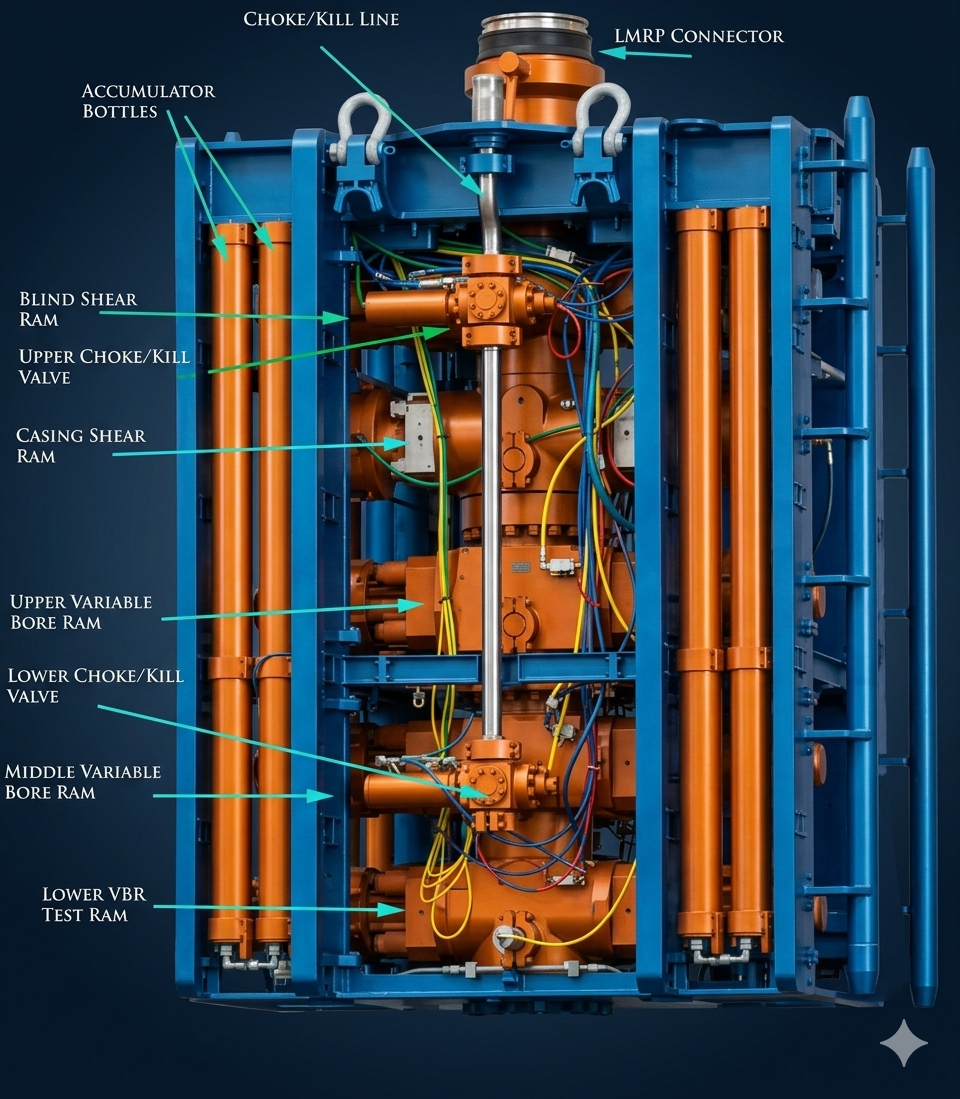
Fig: Subsea BOP assembly diagram
Step-by-Step Energy Transfer Sequence in a Subsea BOP Accumulator
The energy used to close a BOP ram is supplied by compressed nitrogen gas stored in accumulator bottles. The hydraulic fluid simply acts as the medium that transfers this energy to the BOP actuator.
The full sequence can be understood in seven operational stages.
1. Nitrogen Gas Precharge – Establishing the Energy Storage Medium
Each accumulator bottle is precharged with nitrogen gas before hydraulic fluid is introduced.
Inside the accumulator is either:
a flexible bladder, or
a piston separating gas and hydraulic fluid
Nitrogen fills the gas chamber or flexible bladder, while hydraulic fluid occupies the remaining area inside the bottle. This separation ensures the gas does not mix with the hydraulic oil.
Nitrogen is used because it is:
chemically inert
non-flammable
stable under high pressure
Using air or other gases could introduce moisture or combustion risk.
Typical precharge practices include:
1,000 psi precharge for a 3,000 psi working pressure system
1,500 psi precharge for a 5,000 psi working pressure system
The nitrogen behaves like a compressed spring that stores potential energy. The amount of stored energy depends on:
precharge pressure
accumulator volume
system operating pressure.
Proper precharge pressure is critical. If precharge is too low, the accumulator will not deliver sufficient fluid volume to operate BOP functions reliably.
2. Hydraulic Fluid Compression – Charging the Accumulator System
Once the nitrogen precharge is established, the BOP control system pumps begin charging the accumulator bank.
Hydraulic pumps force fluid into the accumulator bottle through the fluid port. As hydraulic fluid enters:
the bladder or piston moves
the nitrogen gas compresses
gas pressure increases
This compression stores energy according to Boyle’s Law, which states that gas pressure increases as volume decreases.
During this stage:
pumps gradually increase pressure
nitrogen compression stores energy in the system.
The accumulator is typically charged until system pressure reaches approximately 3,000–5,000 psi, depending on the BOP control system design.
At this point, the pumps shut off, and the accumulator bank becomes a stored hydraulic energy reservoir.
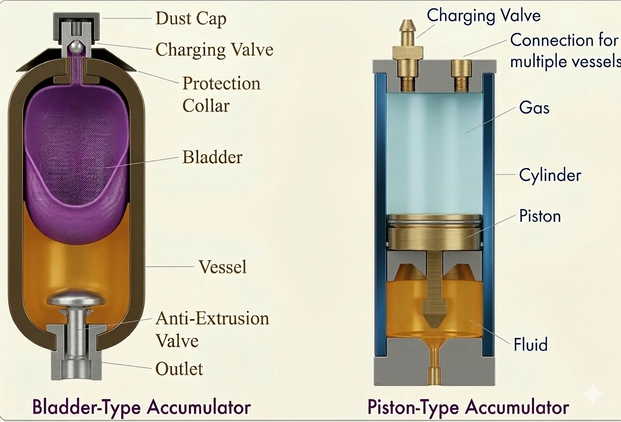
Fig: Accumulator Bottle Construction
3. Stored Potential Energy – Instantaneous Power Available at the Seafloor
When fully charged, the accumulator bottle stores significant potential energy in compressed nitrogen gas. This energy is immediately available to operate BOP functions without relying on surface pumps.
This capability is essential for several critical well control actions:
closing pipe rams
shearing drill pipe using blind shear rams
activating connectors
executing an Emergency Disconnect Sequence (EDS)
Regulatory and industry standards require that accumulators contain sufficient stored energy to close BOP preventers within specific response times. For example, typical API guidance requires that ram preventers close within 30 seconds, while annular preventers should close within 30 seconds for smaller units and up to 45 seconds for larger annular BOPs, measured from function activation to complete sealing.
4. Control Valve Activation – Commanding the BOP Function
When a BOP function is initiated from the rig, a sequence of electrical and hydraulic actions releases the stored energy in the subsea accumulator system.
First, the driller or subsea control operator selects the required BOP function from the rig control panel. This command is transmitted as an electrical signal through the multiplex control system, which carries the signal from the rig to the subsea control pods mounted on the BOP stack.
Inside the control pod, the incoming signal activates a solenoid-operated pilot valve. A solenoid valve is a small, electrically controlled valve that acts as the first trigger in the hydraulic control sequence.
When the solenoid valve is energized, it allows hydraulic pilot pressure to shift a larger hydraulic control valve located in the control pod. This larger valve controls the actual flow of hydraulic fluid needed to operate the BOP components.
Once the hydraulic control valve shifts, it opens the flow path between:
Accumulator bank → Hydraulic line leading to the BOP actuator
This action connects the stored hydraulic energy in the accumulator bank to the specific actuator that must perform the function. At this moment, the energy stored in the compressed nitrogen gas becomes available to move hydraulic fluid through the system and operate the required BOP component.
5. Hydraulic Fluid Displacement – Energy Release from Gas Expansion
After the hydraulic control valve opens, the accumulator begins delivering stored energy to the system.
Inside the accumulator bottle, the compressed nitrogen gas starts to expand. As the gas expands, it pushes against the bladder or piston, separating it from the hydraulic fluid. This movement forces hydraulic fluid from the accumulator bottle into the hydraulic lines.
In simple terms, the expanding gas acts like a powerful spring, pushing the hydraulic fluid out of the accumulator. This process converts the stored potential energy of the compressed gas into hydraulic pressure and flow.
The pressurized hydraulic fluid then travels through the subsea hydraulic lines toward the actuator that has been selected, such as a ram preventer, annular preventer, or connector.
The speed and volume of hydraulic flow depend on several factors, including:
the pressure stored in the accumulator
the size of the control valve opening
the diameter and length of the hydraulic lines
Because the accumulator banks are mounted directly on the subsea BOP stack, the hydraulic fluid only has to travel a short distance to reach the actuator. This local energy storage enables the system to deliver high-pressure hydraulic flow almost instantly, which is critical for rapid and reliable well-control response.
6. BOP Actuator Piston Movement – Converting Hydraulic Pressure into Mechanical Force
Once the pressurized hydraulic fluid leaves the accumulator system, it flows through the subsea hydraulic lines and enters the ram actuator cylinder on the BOP.
Inside this actuator cylinder is a large hydraulic piston. When the high-pressure hydraulic fluid enters the cylinder, it acts on the surface area of this piston. The pressure exerted by the fluid pushes the piston forward along the cylinder.
This movement represents a key energy conversion step in the system. At this point:
Hydraulic pressure from the fluid is applied to the piston
The piston begins to move forward inside the actuator housing
The hydraulic energy is converted into mechanical force
Because the actuator piston typically has a large surface area and is driven by very high hydraulic pressure, the resulting mechanical force is extremely powerful. The total force generated depends mainly on three factors:
BOP bore size – larger BOPs require larger actuators and greater force
Hydraulic system pressure – typically in the range of 3,000–5,000 psi
Actuator piston area – larger pistons generate greater force at the same pressure
This large mechanical force is essential because the BOP must perform several demanding tasks under extreme well conditions. The actuator force must be sufficient to:
Overcome wellbore pressure acting against the closing rams
Shear drillpipe if a blind shear ram is activated during an emergency
Compress sealing elements to create a reliable pressure seal inside the BOP
Only with sufficient closing force can the BOP reliably isolate the well and maintain well control under high-pressure conditions.
7. Ram Closure – Securing the Well
As the actuator piston moves forward, it directly drives the ram blocks located inside the BOP body. Piston movement is transmitted via mechanical linkages that push the rams horizontally across the wellbore.
The final action that occurs depends on the type of ram installed in that particular BOP cavity.
Pipe Rams
Pipe rams are designed to close around the drillpipe or tubing in the well. When activated, the ram blocks move toward each other and seal tightly around the outside diameter of the pipe. This allows the well to remain sealed while the pipe remains in the hole.
Blind Shear Rams
Blind shear rams perform a more critical emergency function. When activated, they first cut through the drillpipe or tubing present in the wellbore. Immediately after shearing the pipe, sealing elements in the rams close together to fully seal the wellbore.
This function is particularly important during emergency disconnect scenarios when the rig must separate from the well quickly.
Connector or Latch Actuators
In some cases, hydraulic actuators are also used to operate connectors or latching mechanisms, such as those used to disconnect the Lower Marine Riser Package (LMRP) from the BOP stack during an emergency disconnect sequence.
Once the rams or connectors reach their final position, the hydraulic pressure applied to the actuator is maintained. The hydraulic fluid remains trapped within the actuator chamber, holding the piston in place and maintaining the required sealing force against the wellbore pressure.
This ensures that the well remains securely isolated until further operations are performed.
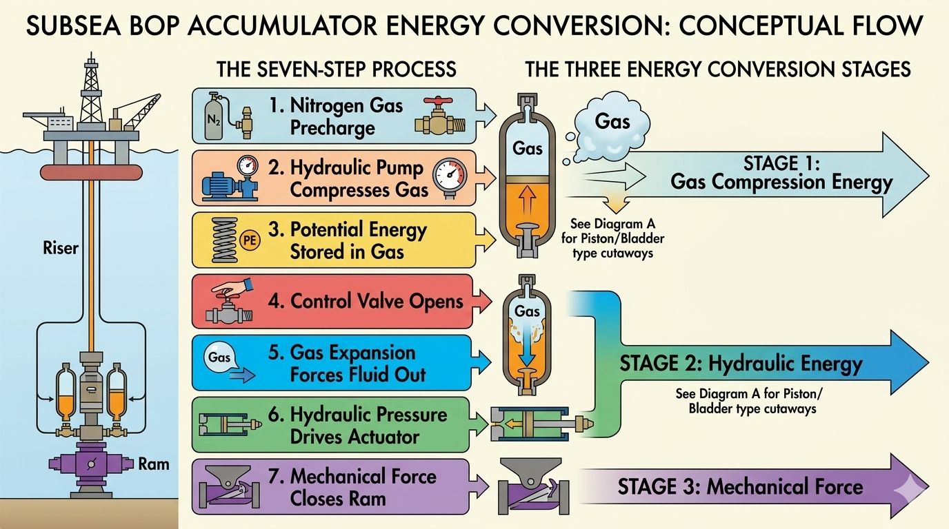
Fig: Conceptual Energy Flow Diagram
Key Engineering Insight for Drilling Professionals
One common misunderstanding in BOP accumulator systems is the belief that hydraulic fluid itself stores the operating energy.
In reality, the true source of stored energy is the compressed nitrogen gas inside the accumulator bottles.
The nitrogen gas behaves like a compressed spring. When compressed during charging, it stores potential energy. When a BOP function is activated, the gas expands, releasing the stored energy.
The hydraulic fluid plays a different role. It primarily serves as:
The energy transmission medium, carrying energy from the accumulator to the actuator
The force transfer medium, transmitting pressure to the actuator piston that moves the rams
Without compressed nitrogen gas, the system would not be able to store energy locally at the BOP stack. The accumulators would simply be containers of hydraulic fluid with no stored power.
It is the gas compression and expansion process that allows the BOP system to deliver large amounts of hydraulic energy instantly, an essential capability for rapid and reliable well control in deepwater drilling operations.
Frequently Asked Questions (FAQ)
Why is nitrogen used in BOP accumulators instead of air?
Nitrogen is inert, dry, and non-flammable. Compressed air contains oxygen and moisture, which could create corrosion, instability, or combustion hazards in high-pressure systems.
2. What happens if the accumulator loses nitrogen precharge?
Loss of precharge drastically reduces the usable hydraulic fluid volume. In extreme cases, the accumulator may deliver no stored energy, preventing reliable BOP operation.
3. Why are many accumulator bottles installed on subsea stacks?
Deepwater hydrostatic pressure compresses nitrogen, reducing its usable volume. Installing multiple bottles ensures sufficient stored hydraulic energy for all critical BOP functions.
4. Can BOP rams operate without surface pumps?
Yes. Accumulators are specifically designed to allow BOP functions to operate using stored energy alone if surface pumps are unavailable. However, once the stored energy in the accumulator bottles is depleted, surface pumps are used to recharge the pressure for the next use.