Foundational Concepts of Hole Cleaning in Drilling Operations
Share Your Thoughts and Additional Information
Hole cleaning is the backbone of trouble-free drilling. Every meter drilled generates rock cuttings that the drilling fluid must lift out of the wellbore and carry to the surface. When hole cleaning performs well, operations achieve good ROP, predictable torque and drag, and clean trips. When it fails, problems escalate rapidly into a stuck pipe, losses, kicks, or lost hole sections. Good hole cleaning is non-negotiable; it separates a planned well from an expensive problem.
Why Hole Cleaning Matters in Every Well
Regardless of depth, formation type, deviation, or drilling system, the principles of hole cleaning remain essential. Cuttings that are not removed effectively will accumulate in the annulus, leading to a range of operational issues such as:
Increasing torque and drag
Pack-offs and stuck pipe
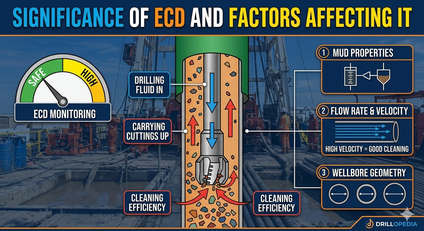
Higher Equivalent Circulating Density (ECD)
Excessive wear on the BHA and surface equipment
Delays, NPT, and rising well cost
More tasks involving higher crew exposure and operational risk
Reduced ROP due to regrinding of cuttings.
Effective hole cleaning provides:
Safe pressure window management between pore and fracture gradients.
Smooth connections and trips without overpull or fill.
Successful casing or liner runs to TD.
Reduced non-productive time and overall well costs.
Improved drilling efficiency.
2. Understanding Cutting Generation in Drilling Operations
2.1 What Are Cuttings and How Are They Generated
Cuttings are small pieces of formation rock that are mechanically removed by the drill bit as it breaks and penetrates the formation. Their size, shape, and quantity are influenced by several factors, including the type of bit used, the strength and texture of the formation, and the drilling parameters applied on the surface. As the rate of penetration (ROP) increases, the bit generates a larger volume of cuttings over a shorter period, increasing the solids load the drilling fluid must carry up the annulus.
2.2 Types of Solids Present in the Wellbore
Not all solids circulating in the wellbore are the same. They differ in origin, size, and ease of transport by the drilling fluid. The main categories are described below.
a. Cuttings
These are the primary solids produced directly by the bit as it drills ahead. If the annular velocity is sufficient and the drilling fluid has suitable rheology, cuttings can usually be removed from the well with relative ease. However, they can break down into smaller pieces, known as fines, due to:
Mechanical degradation from the drill string or BHA rotation.
Chemical reactions in water-based muds, especially when shale cuttings absorb water, hydrate, or disperse.
b. Fines (Low-Gravity Solids)
Fines are small particles typically less than about 74 microns in size. They form when cuttings or cavings are crushed, ground, or chemically dispersed. These solids are problematic because they tend to accumulate in the mud system and:
Increase viscosity and plastic viscosity (PV).
Reduce drilling efficiency and ROP.
Raise circulating pressure losses.
Accelerated wear on pumps and mechanical components.
Fines are commonly detected in shale shaker underflow, mud checks, and retort analyses.
c. Cavings
Cavings are large pieces of formation that fall from unstable wellbore walls, often measuring 1–2 inches or more. They typically appear flat, splintered, or oblong, depending on the failure mechanism. Because of their size and density, cavings are more challenging to transport than standard cuttings. Their presence usually signals a wellbore stability concern, such as:
Insufficient mud weight.
Reactive shale swelling or sloughing.
Mechanical collapse from stress imbalance.
Corrective actions often include adjusting mud weight, improving inhibition, or modifying drilling practices.
d. Swarf
Swarf consists of metal fragments generated during milling operations or from metal-to-metal wear in the BHA. These are heavy, irregular pieces that settle easily and are challenging for drilling fluid to lift. Swarf is usually handled through specialized clean-out or milling practices rather than standard hole cleaning routines.
e. Junk
“Junk” refers to any foreign material that accidentally enters the wellbore, such as dropped tools, hardware, or loose components. These items cannot be removed through normal circulation and instead require fishing tools and dedicated recovery operations.
f. Cement
When hardened cement is drilled out or breaks off from the casing annulus, it forms solid fragments that behave similarly to cavings. These pieces are heavy and rigid, so they must be transported with adequate annular velocity and proper mud properties to avoid settling.
2.3. Volume of Cuttings Generated
The number of cuttings produced during drilling is mainly controlled by hole size and rate of penetration. As the hole diameter increases, the volume of rock removed rises sharply because the bit is cutting a much larger cross-section of formation. This means that large surface and intermediate hole sections can generate large volumes of cuttings, even at moderate ROP.
For example, drilling a 17½-inch hole at 200 ft/hr removes roughly 334 cubic feet of rock per hour — enough to fill an entire railcar in less than one shift. Large hole sections, therefore, generate massive solids loads that demand high flow rates and well-tuned mud properties.
The key message is that large hole sections produce very high solids loads, which must be managed carefully. Effective removal requires:
High, consistent flow rates to lift and carry the cuttings.
Well-tuned rheology and gel strengths so the mud can suspend and transport the solids.
Proper solids control equipment to handle the increased volume at the surface.
Without these measures, the annulus can become overwhelmed, leading to poor hole cleaning and associated drilling problems.
2.4. Transport of Cuttings to Surface
After the drill bit generates cutting, the particles immediately become solid particles suspended in the drilling fluid. Its motion through the wellbore is controlled by two key concepts: settling velocity and slip velocity.
a. Settling Velocity
Settling velocity is the rate at which a particle falls through a static fluid. It depends on the particle’s size, density, and shape, as well as the viscosity of the fluid around it.
b. Slip Velocity
Slip velocity is the rate at which a particle falls relative to a moving fluid. Even when fluid is flowing upward in the annulus, the cutting still tries to move downward due to gravity. The difference between the upward fluid velocity and the particle’s downward slip velocity determines whether the cutting is carried out of the hole or begins to settle.
Slip velocity is much higher in water because it has low, constant viscosity and no yield point.
In non-Newtonian drilling muds, higher low-shear viscosity and yield stress reduce slip velocity, helping keep cuttings suspended and improving transport.
Key Operational Point
Cuttings always attempt to fall straight downward, regardless of the well’s inclination. To transport solids effectively, the upward fluid velocity must be greater than the cutting’s slip velocity. If the fluid cannot outpace the particle’s natural settling tendency, the cutting will accumulate in the annulus.
2.5 Influence of Fluid Type (Newtonian vs. Non-Newtonian)
Water (Newtonian Fluid)
Water has a constant viscosity that does not change with shear. As a result, the settling behavior of particles is straightforward and predictable. However, water offers very limited carrying capacity, especially at low flow rates.
Drilling Mud (Non-Newtonian Fluid)
Most drilling muds behave as non-Newtonian fluids, meaning their viscosity changes under shear. This property is beneficial for cutting transport:
Shear-thinning behavior reduces viscosity at high flow rates, enabling the fluid to flow more efficiently through the wellbore.
At low shear rates, the mud becomes more viscous, which helps suspend particles.
Yield point and gel strength prevent cuttings from rapidly settling when pumps are stopped during connections or surveys.
These characteristics make drilling mud far more effective for cleaning the hole than Newtonian fluids like water.
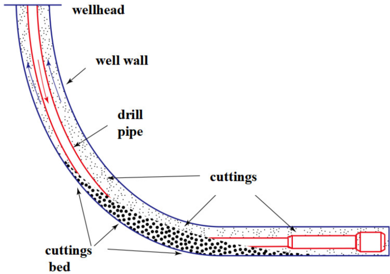
2.6 Why Cuttings Beds Form (Fundamental Concept)
Cuttings are always acted on by gravity and naturally attempt to fall vertically downward. However, in a deviated or horizontal wellbore, the geometry prevents them from falling straight down. Instead, they settle only a short distance from the hole before shifting toward the low side of the hole, a behavior known as the Boycott effect.
Once on the low side, they accumulate and form cutting beds. A cuttings bed will form when the annular velocity is not high enough to lift these solids back into the flow stream. Once established, a cutting bed can:
Grow quickly, especially in long lateral sections or low-flow conditions.
Become unstable and avalanche in the 40°–65° inclination range, causing sudden surges of solids.
Lead to pack-off, stuck pipe, and high torque and drag.
Understanding how and why these beds form is essential for selecting the proper flow rate, rheology, and mechanical agitation needed to maintain clean hole conditions.
3. How Cuttings Behave in the Annulus
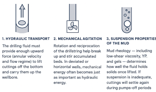
Effective cutting transport is controlled by three main forces working together in the wellbore.
3.1. Hydraulic Lift
This is the ability of the drilling fluid to physically lift cuttings off the low side of the hole. It depends mainly on annular velocity and the flow regime.
In vertical wells, higher flow rates generate more turbulent flow, providing stronger lifting power.
In deviated and horizontal wells, annular flow becomes more laminar in nature because the drillpipe lies on the low side, creating an eccentric annulus. This geometry produces stagnant zones and reduces the effective Reynolds number on the low side, making it difficult to achieve true turbulence. As a result, cuttings depend more on the mud’s low-shear rheology and yield point to help move, roll, or lift them along the annulus.
3.2. Mechanical Agitation
This comes from drillpipe rotation. When the pipe turns, it disturbs the cuttings sitting on the low side of the hole. Even moderate rotation helps break up and erode cutting beds, making it easier for the fluid to lift them. Without rotation (e.g., sliding while steering), cuttings settle more quickly, and beds can form more quickly.
3.3. Fluid Suspension
Once the mud lifts the cuttings, it must also hold them in the flow until they reach the surface. This depends on the mud’s Yield Point (YP) and its low-shear viscosity, typically represented by the 6-rpm and 3-rpm Fann readings.
Adequate YP keeps particles suspended as the mud moves.
Strong low-shear viscosity prevents cuttings from settling during pump slowdowns or short flow interruptions.
Together, hydraulic lift, mechanical agitation, and fluid suspension determine how efficiently the wellbore stays clean during drilling.
4. What Happens When Hole Cleaning Declines
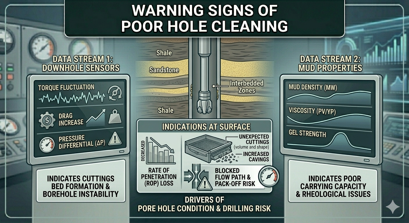
Hole cleaning issues rarely occur all at once. Instead, they develop progressively as cuttings begin to behave differently in the annulus. Long before a pack-off or stuck pipe incident, the well usually provides several early warning signs that conditions are deteriorating. Recognizing these subtle changes is critical for preventing more serious problems.
Common Early Indicators
Reduced or inconsistent cuttings at the shakers while ROP remains unchanged
When the bit continues to drill efficiently but fewer cuttings reach the shakers, it often means solids are beginning to settle in the hole rather than being transported to the surface.
Cuttings that look small, rounded, or poorly defined
This appearance usually indicates that cuttings are being recirculated and mechanically ground by the bit or drillstring, a sign that solids are not being removed on the first pass.
Gradual increases in torque and drag
As cuttings accumulate on the low side or form beds, the drillstring encounters more resistance, which shows up as rising torque while rotating and increasing drag during movement.
Rising or unstable ECD trends
Fluctuating or elevated ECD can occur when cutting beds restrict the annular path, leading to increased frictional pressures and inconsistent hydraulics.
Overpulls or fill during connections and trips
Unexpected drag, difficulty picking up, or finding fill at the bottom often indicates a developing cutting bed or settled solids along the annulus.
Identifying these signs early is one of the most effective ways to prevent serious downhole events such as pack-off, stuck pipe, or wellbore instability.
5. The Importance of Process Discipline
Effective hole cleaning is not the result of a single technique; it requires consistent, disciplined execution of multiple practices throughout the drilling operation. These include:
Maintaining proper flow rates and drillstring rotation
Adequate annular velocity and continuous mechanical agitation help keep solids suspended and prevent low-side buildup.
Monitoring and adjusting drilling fluid properties
Rheology, density, and solids content must be controlled to ensure the mud can transport and suspend cuttings.
Keeping ROP within the well’s carrying capacity
Drilling too fast can overwhelm the mud system, leading to excessive solids loading and poor transport efficiency.
Circulating long enough before making connections or starting trips
This ensures most cuttings are removed before pumps are stopped or pipe movement begins.
Watching for and responding to early warning signs
Timely action when indicators appear is essential for preventing more severe hole problems.
References:
Roy, S. and Power, D. 2002. Using Real-Time Hydraulics Modeling to Complement Annular-Pressure-While-Drilling Data. Paper AADE-02-DFWM-HO-37, AADE Technology Conference “Drilling & Completion Fluids and Waste Management”, Houston, Texas, USA, 2–3 April.
Larsen, T.I., Pilehvari, A.A., and Azar, J.J. 1997. Development of a New Cuttings-Transport Model for High-Angle Wellbores Including Horizontal Wells. SPE Drill & Compl 12 (2): 129–135. https://doi.org/10.2118/25872-PA.
O.C.T.G. Procter Consultancy Ltd. 2000. ABC of Hole Cleaning. Technical Note NS-17, Aberdeen, Scotland, UK.
Zamora, M., Roy, S., Slater, K., and Troncoso, J. 2013. Real-Time ECD Management: A Systematic Approach to Hole Cleaning and Wellbore Stability. Paper SPE/IADC-163483-MS presented at the SPE/IADC Drilling Conference, Amsterdam, The Netherlands, 5–7 March.
Hemphill, T. and Ravi, K. 2019. Best Practices in the Optimization of Drilling Fluids and Hydraulics for Hole Cleaning in Deviated and Horizontal Wells. Paper AADE-19-NTCE-046, AADE Fluids Conference, Denver, Colorado, USA.
Figure 1: Adapted from Wang, Z. et al. 2023. A Review of the Settling Law of Drill Cuttings in Drilling Fluids. Processes 11(11):3165. https://doi.org/10.3390/pr11113165 (open access, MDPI).
Disclaimer: This guide synthesizes and paraphrases industry best practices from referenced sources for educational and field-reference purposes only. It does not reproduce copyrighted material verbatim and is not official company policy or engineering advice. All information belongs to the original authors and publishers who retain full rights. No claim of original authorship is made for referenced concepts, and the document is distributed in good faith for drilling professionals.