
Well Control Concepts in Well Intervention
Completion, Workover, Wireline and Coiled-Tubing Operations
Share Your Experience and Comments
Key Questions Answered
Why does well control during interventions differ fundamentally from drilling operations?
What barrier, verification, and equipment principles are required to ensure primary and secondary containment during well intervention?
How are well-killing methods evaluated, and what operational risks and safeguards must be managed?
1. Distinguishing Intervention Well Control from Drilling
While the primary objective of well control remains consistent across all operations, 'preventing uncontrolled fluid flow and maintaining full pressure containment,' well intervention operations present a distinct set of operational dynamics, barrier configurations, and risk profiles:
Drilling Operations: Primary well control relies predominantly on a hydrostatic fluid column, while the Blowout Preventer (BOP) stack serves as the secondary barrier for shut-in and pressure containment. Open-hole conditions and dynamic formation pressures represent the primary operational focus.
Intervention Operations: Interventions deal with completed, pressurized wells containing live hydrocarbons, completion tubing, packers, a Downhole Safety Valve (DHSV), and a production tree. Operations frequently alter existing barriers, while circulation pathways are often restricted or non-existent.
Well planning must account for pre-existing barriers, potential modifications to those barriers, pressure-control equipment (PCE) interfaces, and specific operational phases. Intervention well control is not simply drilling well control performed with smaller equipment; it requires a specialized engineering and operational approach.
2. Barrier Philosophy and Verification
Establishing Barriers
Identify all potential flow paths and establish the required barriers for each operational phase and transition.
Adhere strictly to regulatory mandates, company policy, and the approved well program. Standard governance frameworks require a minimum of two tested, independent barriers, with specific configurations and acceptance criteria defined by the operation.
A well barrier envelope may consist of several pressure-containing components that collectively prevent unintended flow, such as a tree valve, lubricator, and stuffing box arranged in series during wireline intervention. The presence of multiple valves, seals, or pressure-control devices does not, by itself, establish the existence of multiple independent barriers.
Barrier independence must be assessed from the complete barrier arrangement, including the functions of its elements, their verification, and any shared or interdependent components. The failure of one barrier should not compromise the integrity of the other. Where common barrier elements cannot be avoided, their implications must be assessed and appropriate risk-reduction measures implemented.
During well intervention, the barrier schematic must therefore identify the actual primary and secondary barriers for the specific operating configuration rather than simply counting the pressure-control components.
Ensure all barrier elements are qualified to withstand maximum anticipated differential pressures, temperatures, fluid chemistries, and mechanical loads.
Barrier Elements and Envelopes
Well Barrier Elements (WBEs): Individual physical components that prevent fluid flow, including production casing, tubing, production packers, tubing hangers, surface tree valves, qualified bridge plugs, pressure-control equipment, and hydrostatic fluid columns.
Well Barrier Envelope: The continuous envelope formed by interconnected WBEs that prevents fluid movement along a defined flow path.
Schematics: Phase-specific well barrier schematics must clearly illustrate envelope boundaries, mechanical flow paths, verification status, and monitoring points across all conduits, including tubing, annuli, and completion accessories.
Verification and Documentation
Verify every WBE through standardized pressure, inflow, or function testing prior to relying on it as a barrier.
Predetermine and document all test parameters, including target pressure, hold duration, pressure application direction, maximum allowable leak rates, and pass/fail criteria.
Note: A successful pressure test confirms static pressure integrity but does not guarantee dynamic function or performance across all potential differential pressure regimes.
Formally record and communicate barrier status, test charts, operating envelopes, and approved deviations to all field personnel.
Never assume a closed DHSV is a qualified barrier without performing physical inflow or pressure testing to verify its sealing capability and functional integrity.
3. Pressure Control Equipment (PCE)
Equipment selection depends directly on the conveyance method, well configuration, maximum anticipated surface pressure, and barrier logic.
Wireline Operations
Lubricators: Provide pressure containment during the deployment and retrieval of tool strings.
Stuffing Boxes / Grease Heads: Maintain a continuous dynamic seal around moving wireline or slickline strands.
Wireline BOPs: Provide positive shut-in capability. If wireline cutting capability is required, the shear rams must be qualified to cut the specific line type, tool string, or armor in use under wellbore pressure.
Coiled Tubing Operations
Stripper Assemblies: Form the primary dynamic pressure seal around the moving coiled tubing string during deployment and retrieval.
BOP Stack: Typically configured with pipe, blind, shear, and slip rams arranged to perform specific well-control actions.
Dual Check Valves: Installed at the bottom of the coiled tubing string to prevent backflow up the pipe; these serve as a component within the string but do not replace the primary dynamic surface sealing barrier.
Verify all mechanical load limits, pressure ratings, fluid compatibility, and emergency hydraulic functions before commencing operations.
Completion and Workover Operations
Workover activities often require unseating packers, pulling tubing, manipulating plugs, or replacing tree components, directly impacting pre-existing barrier envelopes.
Verify secondary containment integrity before removing or unseating any primary barrier element.
The well program must explicitly state the containment barrier configuration during nipple-up or nipple-down transitions of the Xmas tree and Blowout Preventer.
Confirm all PCE connections, flanges, and adapters match the working pressure ratings and fluid trim requirements of the wellhead assembly.
Emergency Shearing Functions
Select and field-verify shear-seal or cutting devices specifically for the conveyance in use (e.g., heavy-wall coiled tubing, wireline, or work string). Do not assume a shear ram will cut non-standard tool strings or drill collars without prior qualification.
Clear activation criteria, operating pressure limits, and emergency sequence procedures must be defined in the well program and reviewed during pre-job safety meetings.
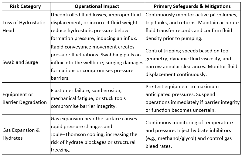
4. Principal Intervention Risks
5. Standard Operational Lifecycle Practices
Phase 1: Pre-Job Execution
Thoroughly review well history, completion schematics, annulus pressure history, and prior integrity logs.
Review offset well conditions and operations (such as depleted reservoirs, nearby injection wells, etc.) to assess any potential impact on planned well intervention operations.
Develop phase-specific well barrier schematics for every stage of the intervention.
Inspect, function-test, and pressure-test all PCE, surface connections, and emergency shutdown systems.
Conduct pre-job safety meetings detailing individual roles, barrier ownership, monitoring criteria, emergency procedures, and Stop-Work Authority.
Phase 2: On-Job Execution
Continuously track well barrier status throughout operational transitions.
Monitor real-time wellhead pressures, annulus pressures, fluid injection rates, gain/loss volumes, and returns.
Immediately suspend operations and secure the well if anomalous trends appear or if barrier integrity becomes questionable.
Document and obtain formal management approval for any field deviations or MOCs (Management Of Change) prior to execution.
Phase 3: Post-Job Execution
Document final wellbore status, barrier configurations, pressure test records, and handover conditions.
Record equipment performance issues, non-conformances, and operational lessons learned.
Communicate outstanding well integrity concerns or monitoring requirements to the production operations team during handover.
6. Governance, Industry Standards, and Competence
Intervention well control relies on standardized governance frameworks and verified personnel competence:
NORSOK Standard D-010: Defines international requirements for well integrity, barrier envelopes, testing protocols, and acceptance criteria across well lifecycles.
API Standard 53: Outlines testing and maintenance standards for BOP systems. Note: Primarily written for drilling operations, it must be supplemented with intervention-specific standards (e.g., API RP 16ST for Coiled Tubing or API RP 59) during interventions.
ISO 16530-1: Establishes a comprehensive framework for managing well integrity throughout the well's entire lifecycle.
IOGP Report 476: Details recommended training, examination, and certification frameworks for well-control competence across drilling, completion, workover, and intervention disciplines.
IWCF / IADC WellSharp: Provide role-specific training pathways and standardized certification for intervention personnel.
Local regulatory frameworks, operator policies, equipment limitations, and the approved well program remain the governing authorities for all well intervention operations.
References
Standards Norway. NORSOK Standard D-010: Well Integrity in Drilling and Well Operations. Rev. 4, June 2013.
American Petroleum Institute. API Standard 53: Blowout Prevention Equipment Systems for Drilling Wells. American Petroleum Institute.
International Organization for Standardization. ISO 16530-1:2017, Petroleum and Natural Gas Industries—Well Integrity—Part 1: Life Cycle Governance. ISO, 2017.
International Association of Oil & Gas Producers. Recommendations for Enhancements to Well Control Training, Examination and Certification. IOGP Report 476, 4th ed., 2023.
International Association of Oil & Gas Producers. Review of Well Control Incidents. IOGP Information Sheet INF014, 2021.
Norwegian Ocean Industry Authority (Havtil). The Activities Regulations, Section 85: Well Barriers.
Society of Petroleum Engineers. Using Schematics for Managing Well Barriers. Journal of Petroleum Technology.